What is the EER value and how is it calculated? The EER (energy efficiency ratio) defines the performance number of a refrigeration unit, i.e. the ratio of the cooling produced to the consumption of electric energy.
EER =
Q0PKL
How is the ratio of cooling capacity to the clamp achievement (EER) of the acr rental machines? Dependent on air or water-cooled chillers, the efficiency varies considerably. Our large cooling systems with centrifugal-compressors for example reach EER values of > 5. For the standard product assortment, the following values can be assumed..
– EER in deep cooling machines 1 to 2
– EER in air cooled chillers 2.5 to 3.5
– EER in water cooled chillers 3.5 to 6
Is there a guideline for the variation of the cooling capacity per° C temperature change of the cold water temperatures? As a rule of thumb, per K temperature reduction the cooling capacity decreases by about 4%.
Is there a guideline for the flow rate in dependence of the cooling capacity?
As a guideline, for the flow rate per kW cooling capacity, dependent on ∆t (temperature difference between cold water inlet and discharge) the following values can be assumed.
Δt 4K ≈ 215 l/h per kW cooling capacity
Δt 5K ≈ 172 l/h per kW cooling capacity
Δt 6K ≈ 143 l/h per kW cooling capacity
Δt 7K ≈ 123 l/h per kW cooling capacity
Δt 8K ≈ 108 l/h per kW cooling capacity
Δt 9K ≈ 96 l/h per kW cooling capacity
Δt 10K ≈ 86 l/h per kW cooling capacity
In practice the cold water temperature difference is between 5 and 8K
Which tube sizes and couplings are used for which cooling capacities?
On the basis of acr experience, the following tubes and couplings can be used in the various different cooling capacity ranges, up to the maximum length of 100 meters.
Cooling capacity
Tube size
Coupling
< 20 kW
DN 40
Storz C
20 – 40 kW
DN 50
Storz C
40 – 100 kW
DN 80
Storz B
100 – 800 kW
DN 100
Storz A
> 800 kW
DN 125
Storz 125
Wie verhält sich die Kälteleistung in Abhängigkeit des Verschmutzungsfaktors (Fouling Factor)?
Soiling factor
[m2 °C / kW]
Correction factor of the cooling capacity
Correction factor of the power consumption
Correction factor of the performance number (EER)
0.0176
1.000
1.000
1.000
0.0440
0.978
0.986
0.992
0.0880
0.957
0.974
0.983
0.1320
0.938
0.962
0.975
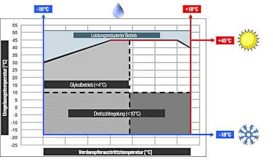
For which operational areas are the air cooled chillers suited? The chillers are suitable for the unrestricted operation at 35°C outside temperature and operate in the capacity restricted mode in ambient temperatures up to 50° C. For use in lower ambient temperatures, the cold water chillers equipped with variable speed ventilators and vaporizer heating are suitable. In this way operation is possible at lower temperatures. At extremely low ambient temperatures and particular locations as well as when light cooling loads prevail, additional measures must be taken.
Image: Application area of air cooled chillers
The sound values of the acr rental machines are specified at a distance of 5m. How much does the sound value decrease when the distance is doubled to 10m? Generally the sound pressure level is specified according to ISO 3744 in a hemispherical field at 1m distance. As a rule of thumb, the sound pressure is reduced by about 4 dB(A) when the distance is doubled. For example a sound pressure level specification of 66dB(A) at 5m distance equates to a sound pressure level of about 62dB(A) at 10 meters, and at 20m about 58dB(A) and so on.
Machine basics:
Wherein do air cooled and water cooled chillers differ? Air cooled chillers (fluid cooler) distinguish themselves through their compact design and are available in a capacity range of 5 – 2,000kW. The refrigerant has a direct heat transition to the air and therefore the liquefaction of the refrigerant is directly passed through to the environment.
Water cooled chillers are more efficient, however through an external drycooler unit they are also substantially more expensive and costlier to install. In the rental segment, the cooling capacity range is between 5 and 4,500kW per unit.
What is the difference between Scroll- and screw compressors? Because the compressor is an especially important part of a refrigeration unit, this question will be answered especially in detail. According to requirements and capacity range, scroll-, screw or centrifugal compressors are implemented.
Scroll compressors Scroll compressors are implemented in a capacity range of 5 – 100kW cooling capacity and are fully hermetically sealed. Several compressors can be used together in a refrigeration circuit. In this way capacity ranges of up to 600kW and more can be reached by the so-called Multiscroll units.
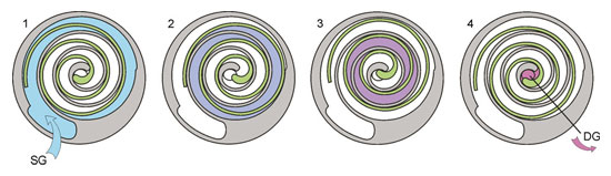
The compression of the refrigerant is achieved by the orbital path of a moving spiral in a fixed spiral at about 2900 RPM at 50Hz.
Image: Compression principles in Scroll compressors (Bitzer)
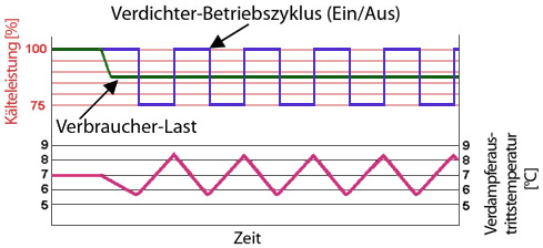
The current power adjustment herewith takes place by activating and deactivating individual compressors. In following example, four compressors provide for 100% cooling capacity. In the case of 85% loading, three compressors are continuously in operation and the fourth is engaged or disengaged as needed. To protect the compressor, the frequency of engaging / disengaging should not exceed six times per hour.
Image: Operating cycle Scroll compressor
Cold water temperature variations through engaging and disengaging of the compressor
Screw compressor
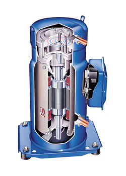
Semi-hermetic-screw compressors are available in a capacity range of 100 – 1,200kW cooling capacity. With up to three separate refrigeration circuits, cooling capacities of over 2.000kW per unit can be achieved. The compression of the refrigerant is achieved by a continuous and on vibrating rotation of the screw at about 2,900 RPM at 50Hz.
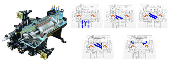
In the following photo, a McQuay single rotor screw compressor is shown. The single rotor screw compressor consists of a main rotor directly connected to the motor and two diametrically opposite, interrelated and geared addition rotors. The simultaneous flow of intake and compression leads to an almost complete cancellation of radial and axial forces and therefore to very slight bearing loads.
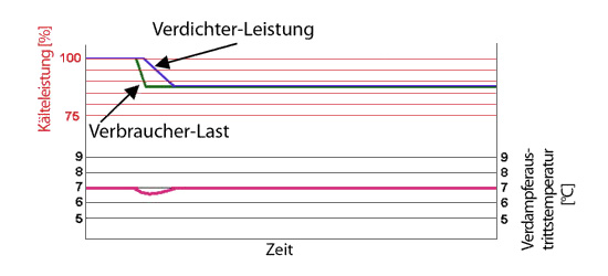
The power adjustment of the screw compressor is step less. According to compressor size and number, a step less power adjustment up to 10% is possible. On the basis of the following example is to be recognized that at a load of about 85% the compressor can be set exactly. According to application or tolerated deviation of the cold water temperatures, this technology that enables an accuracy of ±0.2K (°C), is indispensable.